
If we leave aside the linearity of the electromechanical transducers of the cutter head when recording and the cartridge, when playing the record - which may in any case be reduced to low levels - the majority of the distortion generated in reproduction from records is due to the differences in the various geometries of the recording and reproduction processes.
When a record is recorded, a flat chisel, driven by a moving-coil mechanism rather like a loudspeaker, is drawn in a radial line across the soft, acetate disc. When being played back, a conical (or elliptical) stylus supported on a cantilever rides in an arc across a plastic disc at the end of a pivoted tone arm. This leads to, at least four distortion mechanisms which are described below.
 By far the most discussed of the distortion mechanisms is lateral tracking distortion. This arises due to differences in the path of the recording cutter head, which is driven in a straight-line across the radius of the disc by a worm gear arrangement, and the cartridge which moves in an arc at the end of freely pivoted tone arm. A simple, straight tone arm carries with it the very considerable compromise that the stylus is only on a tangential line to the groove at one point on the record.
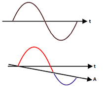
The effect of reading the disc in a direction other than which it was recorded is complex, as the drawing (right) illustrates. Essentially, the sine wave, shown in the upper diagram and recorded tangentially to the disc, is read along axis A. This has the effect of elongating the positive modulation and shrinking the negative: a frequency modulation effect which causes a very serious type of distortion capable of producing a very complex and dissonant distortion.
![]() So far, so serious. However, the mathematics of the geometry of the tone arm path (and the distortion mechanisms) have been well understood since the days of the early, pre-electric gramophone. All modern tone arms are arranged to overhang the centre of the record, and have a "crank" so that the cartridge sits at an angle relative to the tone arm. By these two simple geometrical means, the tracking error (the angle of the cartridge relative to the tangent of the groove) is reduced to a few degrees at any point on the record. When the error angle is this small, the frequency modulation effects are reduced so that the resulting sidebands are equivalent to second harmonic distortion.
So far, so serious. However, the mathematics of the geometry of the tone arm path (and the distortion mechanisms) have been well understood since the days of the early, pre-electric gramophone. All modern tone arms are arranged to overhang the centre of the record, and have a "crank" so that the cartridge sits at an angle relative to the tone arm. By these two simple geometrical means, the tracking error (the angle of the cartridge relative to the tangent of the groove) is reduced to a few degrees at any point on the record. When the error angle is this small, the frequency modulation effects are reduced so that the resulting sidebands are equivalent to second harmonic distortion.
Note that, whilst tracking distortion may be reduced to low levels by correctly setting the overhang and crank angle of the cartridge, the distortion due to this cause may become very great indeed if these are incorrectly set - especially towards the centre of the record. In fact tracking distortion ∝ (tracking angle error/ groove radius) as explained on this page.
Tracing distortions are quite separate from tracking distortions. The origin of all tracing distortion is that a groove cut by a flat-faced chisel is being read by a rounded (conical or elliptical) stylus. Tracing distortion is responsible for the majority of distortion (and not just harmonic distortion) when reproducing gramophone records. There are three components to tracing distortions: pinch-effect; vertical tracing distortion; and wavelength-loss.
Pinch effect
Constrained as it is to follow a path along the disc radius, the cutter chisel cuts a groove which is only the width of the cutter at the peaks of the wave and which shrinks to a minimum as the wave passes through the zero position. This has the effect of squeezing the stylus up and down in the groove even when the modulation is entirely lateral. This phenomenon is termed, appropriately enough, pinch effect.
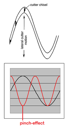 This effect of pinching the stylus in the narrowing groove may be seen to be at a frequency double that of the lateral modulation; because the stylus rises and falls twice over in one cycle of the modulation wave (see the illustration left).
The pinch-effect upon the stylus is greater as the wavelength of the modulation falls. Besides being frequency dependent, wavelength is also a function of the angular velocity of the recording chisel in the groove. In a conventional gramophone record, this velocity falls as the cutter (or stylus) moves towards the centre of the record because the record turns at a constant number of revolutions per minute, but the radius of the groove falls throughout the playing of one side of the disc.
Additionally, the degree of the pinch-effect depends upon the radius of the stylus. Special stylus shapes have been developed to reduce the pinch-effect. Elliptical styli are shaped so that the major axis of the ellipse has the dimensions of a conical stylus and is perpendicular to the groove. This ensures the stylus rides in the groove at the same level as a conical stylus and doesn't wallow about in the bottom of the groove where no information resides. However, the minor axis of the ellipse is arranged to be considerably smaller than the major axis and this is parallel with the groove. By these means, the stylus is less squeezed as the groove narrows in the direction of the stylus travel.
To read more about stylus shapes and groove geometry go here.
Vertical tracing distortion
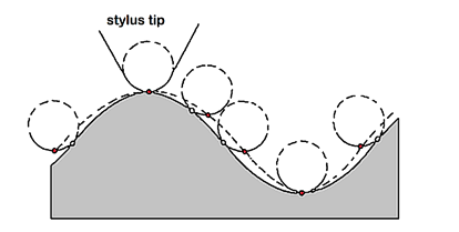 The figure above shows the cross section of a vertically modulated groove (the grey is the disc in cross-section). Whilst the recording is made with a sharp edged chisel, playback is accomplished by means of the spherically rounded cone of the playback stylus. The figure clearly illustrates that the motion of the playback stylus fails to follow the groove's shape. The problem being that the point of contact between the spherical playback stylus and the groove wall wanders as it traces the groove, causing the stylus to trace a path indicated by the dashed line.
Once again, an elliptical stylus helps here as the point of contact wanders less far from the base of the stylus if the stylus is smaller in the direction of groove travel.
Distortion due to vertical tracking angle (VTA) error has many similarities with lateral tracking error and it shares the same mathematical analysis. The origins of vertical tracking error lie in the mechanics of the disc cutting system in which it is impractical to design a cutter system to have a vertical modulation angle of 0�, since this would require the pivot point of the moving system of the cutter to lie in the plane of the record.
Instead, the cutting stylus must itself have a pivot above the disc's surface and the modulation cut into the lacquer must have a modulation angle with respect to the plane of the record surface. This angle is called the Vertical Modulation Angle (VMA). Vertical Tracking Angle and the related Stylus Rake Angle (SRA) are fully explained here.
Wavelength loss (sometimes called tracing loss) is another distortion due to the physical fact that a sharp chisel is used in recording and a rounded stylus is used in reproduction. The sharp chisel is capable of cutting "sharper corners" than the stylus can read and this results in high-frequency loss at shorter recorded wavelengths. The loss is also related to the deformation of the soft PVC as the hard diamond of the styus passes over it. Shorter wavelengths of recorded sound and the degree PVC yields are more of a problem towards the centre of the record. Most cartridges, even those with elliptical styli, manifest a falling frequency response as the groove approaches the centre. Wavelength loss is fully descibed on this page.
The LP Distortion Cancellation algorithm in Stereo Lab corrects for the following distortion mechanisms:
The LPDC algorithm must be applied to needle-drops made prior to RIAA correction because, by this means, the correction is applied in a frequency-dependent way. The algorithm is thus ideally applied to needle-drops made with the Groove Sleuth phono preamplifier.
The LPDC algorithm does not entirely correct for:
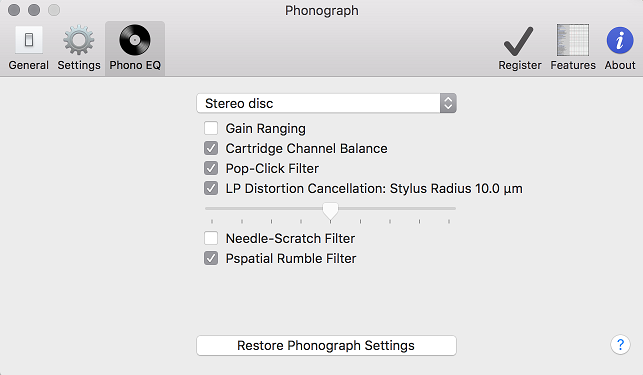
A check box (marked LP Distortion Cancellation) is provided to engage this processing in the LP tab of the settings dialogue. And there is a slider control which should be set according to the stylus type used to play the record. To read more about stylus shapes and groove geometry go here. In short we can summarise that the slider should be set:
Note that single-rate files will be automatically up sampled when LPDC is applied to permit the generation of distortion partials above the single-rate Nyquist limit without causing aliasing.
 A degree of reticence should be excercised in applying LPDC because some record lathe equipment applied something very similar during cutting. In other words, the audio was pre-distorted in such a way as to cancel the effects of pinch effect and lateral tracking distortion on replay. These systems were known by their trade names: Dynagroove, Phase Four and Stereosonic. Unfortunately, records are rarely marked to indicate if this equipment was used or not during mastering.
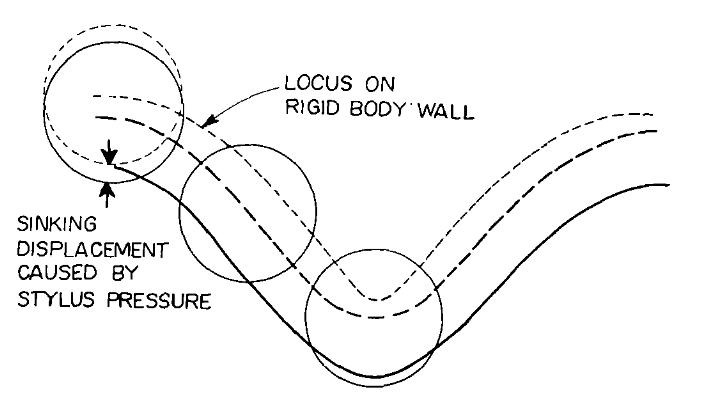
In addition, theoretical work done by Nippon Columbia in the heyday of vinyl records demonstrated that the plastic deformation of the record under the load of the stylus actually compensates for some distortion due to tracing error. (See illustration right1.) To some degree this work was confirmed in empirical studies; although only at low frequencies2.
The values of correction chosen for Stereo Lab are taken from our own direct measurements from many records: not from theoretical studies.
1. Shiga, T. Deformation Distortion in Disc Records. JAES July 1966
2. Barlow, D.A. et al. Groove Deformation and Distortion in Records JAES July/August 1978
Home page
For all support issues, go here.
For Pspatial Audio sales, email: sales@pspatialaudio.com